Thursday, January 9, 2014
Simple 15V And 5V Car Battery Supply Circuit Diagram
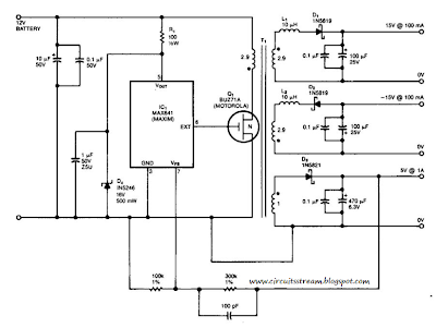

Thursday, December 19, 2013
Low Cost Universal Battery Charger


R2 = See Diagram
C1 = 220uF-35V
D1 = 1N4007
D2 = 3mm. LED
Q1 = BD135
J1 = DC Input Socket
- Ideal for in car use.
- LED charge indication.
- Selectable charge current.
- Charges Ni Cd or NiMH batteries.
- Transforms a mains adapter into a charger.
- Charge cellular phone, toys, portables, video batteries …
- LED function indication.
- Power supply polarity protected.
- Supply current: same as charge current.
- Supply voltage: from 6.5VDC to 21VDC (depending on used battery)
- Charge current (±20%): 50mA, 100mA, 200mA, 300mA, 400mA. (selectable)

Example:
- Mount the transistor together with the heatsink on the PCB, bend the leads as necessary. Take care that the metal back of the transistor touches the heatsink. Check that the leads of the transistor do not touch the heatsink.
Wednesday, December 18, 2013
12V Lead Acid Battery Charger with Indicator

I built this charger many years ago, I think I was still in school back then. On request of a reader of my web site, Im publishing it now, despite being a rather crude circuit. It works, it is uncritical to build, and uses only easy-to-find parts, so it has something in its favor. The downside is mainly the low efficiency: This charger wastes about as much power as it puts into the battery. The charger consists of two stages: The first is a capacitive voltage doubler, which uses a 555 timer IC driving a pair of transistors connected as emitter followers, which in turn drive the voltage doubler proper.

The doubler has power resistors built in, which limit the charging current. The second stage is a voltage regulator, using a 7815 regulator IC. Its output is applied to the battery via a diode, which prevents reverse current and also lowers the voltage a bit. The resulting charge voltage is about 14.4V, which is fine for charging a gelled or AGM battery to full charge, but is too high as a trickle charger, so dont leave this charger permanently connected to a battery.
If you would like to do just that, then add a second diode in series with D3! There is a LED connected as a charge indicator. It will light when the charge current is higher than about 150mA. The maximum charge current will be roughly 400mA. There is an auxiliary output, that provides about 20V at no load (depending on input voltage), and comes down as the load increases. I included this for charging 12V, 4Ah NiCd packs, which require just a limited current but not a limited voltage for charging.

Note that if the charge output is short-circuited, the over-current protection of U2 will kick in, but the current is still high enough to damage the diodes, if it lasts. So, dont short the output! If instead you short the auxiliary output, the fuse should blow. I built this charger into a little homemade aluminum sheet enclosure, using dead-bug construction style. Not very tidy, but it works. Note the long leads on the power resistors. They are necessary, because with shorter leads the resistors will unsolder themselves, as they get pretty hot! The transistors and the regulator IC are bolted to the case, which serves as heat sink. The transistors dont heat up very much, but the IC does.
Monday, December 16, 2013
Simple Battery charger Circuit Diagram

Wednesday, October 9, 2013
Li Ion Battery Charger Circuit
The LP2951 regulator is manufactured by National Semiconductors. The choice of values is from an application note "Battery Charging", written by Chester Simpson. Diode D1 can be any diode from the 1N00x series, whichever is conveniently available. It functions as a blocking diode, to prevent a back flow of current from the battery into the LP2951 when the input voltage is disconnected. Charging current is about 100+mA, which is the internally-limited maximum current of the LP2951. For those wondering, this is compatible with just about any single-cell li-ion battery since li-ion can generally accept a charging current of up to about 1c (i.e. charging current in mA equivalent to their capacity in mAh, so a 1100mAh li-ion cell can be charged at up to 1100mA and so on).
Circuit diagram:
 Li-Ion Battery Charger Circuit diagram
A lower charging current just brings about a correspondingly longer charge time. IMHO 100mA is quite low, low enough that the circuit can be used for an overnight charger for many typical single-cell li-ion batteries. The resistors are deliberately kept at large orders of magnitude (tens/hundred Kohm and Mohm range) to keep the off-state current as low as possible, at about 2?A. Resistor tolerances should be kept at 1% for output voltage accuracy. The 50k pot allows for an output voltage range between 4.08V to 4.26V - thus allowing calibration as well as a choice between a charging voltage of 4.1V or 4.2V depending on the cell to be charged. The capacitors are for stability, especially C2 which prevents the output from ringing/oscillating.
Parts
IC1 = LP2951, voltage regulator
D1 = 1N4002, General purpose diode
R1 = 2M, 1%, metal-film
R2 = 806K, 1%, metal-film
P1 = 50K, potentiometer
C1 = 0.1uF, polyester
C2 = 2.2uF/16V, electrolytic
C3 = 330pF, ceramic
Source :www.extremecircuits.net
Sunday, October 6, 2013
Simple Battery Charger Circuit Charges Upto 12 NiCD Cells

Friday, October 4, 2013
Lead Acid Battery Charger Circuit 2
The above pictured schematic diagram is just a standard constant current model with a added current limiter, consisting of Q1, R1, and R4. The moment too much current is flowing biases Q1 and drops the output voltage. The output voltage is: 1.2 x (P1+R2+R3)/R3 volt. Current limiting kicks in when the current is about 0.6/R1 amp. For a 6-volt battery which requires fast-charging, the charge voltage is 3 x 2.45 = 7.35 V. (3 cells at 2.45v per cell).

So the total value for R2 + P1 is then about 585 ohm. For a 12 V battery the value for R2 + P1 is then about 1290 ohm. For this power supply to work efficiently, the input voltage has to be a minimum of 3V higher than the output voltage. P1 is a standard trimmer potentiometer of sufficient watt for your application. The LM317 must be cooled on a sufficient (large) coolrib. Q1 (BC140) can be replaced with a NTE128 or the older ECG128 (same company). Except as a charger, this circuit can also be used as a regular power supply.

 Parts List:
R1 = 0.56 Ohm, 5W, WW
R2 = 470 Ohm C2 = 220nF
R3 = 120 Ohm
R4 = 100 Ohm
C1 = 1000uF/63V
Q1 = BC140
Q2 = LM317, Adj. Volt Reg.
C3 = 220nF (On large coolrib!)
P1 = 220 Ohm
Source : www.extremecircuits.net
Monday, September 30, 2013
Simple But Reliable Car Battery Tester
This solution is better than letting the internal voltage regulator set the 12V sample voltage to be feed into the internal voltage divider simply because it cannot regulate 12V when the voltage drops lower (linear regulators only step down). Simply wiring with no adjust, the regulator provides stable 1,25V which is fed into the precision internal resistor cascade to generate sample voltages for the internal comparators. Anyway the default setting let you to measure voltages between 8 and 12V but you can measure even from 0V to 12V setting the offset trimmer to 0 (but i think that under 9 volt your car would not start).

There is a smoothing capacitor (4700uF 16V) it is used to adsorb EMF noise produced from the ignition coil if you are measuring the battery during the engine working. Diesel engines would not need it, but Im not sure. If you like more a point graph rather than a bar graph simply disconnect pin 9 on the IC (MODE) from power. The calculations are simple (default)
For the first comparator the voltage is : 0,833 V corresponding to 8 V
* * * * * voltage is : 0,875 V corresponding to 8,4 V
for the last comparator the voltage is : 1,25 V corresponding to 12 V
Have fun, learn and dont let you car battery discharge... ;-)
e-mail: jonathan.filippi@virgilio.it
Wednesday, September 25, 2013
Low Cost Battery Condition Indicator

The series resistor for the LED needs to be selected for each battery voltage, to limit the current to a safe vale or you could use a fixed resistor and a series trimpot for flexibility. Low battery voltage is indicated by the LED pulsing at around 1Hz. The battery voltage is monitored by transistor Q1 and trimpot VR1. Once the voltage at its base falls below 0.6V, Q1 turns off and Q2 turns on to enable the 2-gate oscillator formed by IC1a and IC1b, which runs at 1Hz. The pulses from this oscillator are inverted by IC1d to gate the LED oscillator on and off. Calibration can be done with a variable bench power supply set to the lowest battery voltage you will accept. Power up the circuit and adjust VR1 until the LED pulses once per second.
Monday, September 2, 2013
Li Ion Polymer Battery Charger Using LTC4098
Li-Ion Polymer Battery Charger Circuit diagram

The voltage on the pin7 (Prog) pin always represents the actual charge current by using the following formula: IBAT =(VPROG/RPROG)x1030 The charge current is programmed using a single resistor from PROG to ground.The program resistor and the charge current are calculated using the following equations :RPROG =1030V/ICHG ; ICHG =1030V/RPROG . The charge voltage will be 4.2V with 0.5 accuracy . As you can see in the schematic circuit this charger is very simple an you need to apply just few easy equations to design a high efficiency Li-Ion Polymer charger .
Battery Voltage Indicator Using SN16889
Battery Voltage Indicator Circuit Diagram
