Showing posts with label supply. Show all posts
Showing posts with label supply. Show all posts
Saturday, January 11, 2014
Dual Regulated Power Supply Circuit Diagram
In this circuit, the 7815 regulatates the positive supply, and the 7915 regulates the negative supply. The transformer should have a primary rating of 240/220 volts for europe, or 120 volts for North America. The centre tapped secondary coil should be rated about 18 volts at 1 amp or higher, allowing for losses in the regulator. An application for this type of circuit would be for a small regulated bench power supply.
Dual Regulated Power Supply Circuit Diagram


Thursday, January 9, 2014
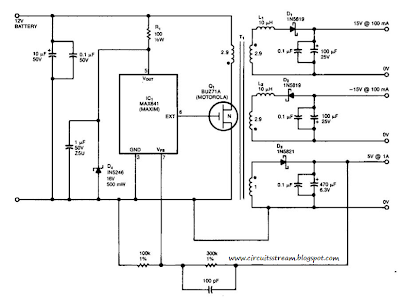
Simple 15V And 5V Car Battery Supply Circuit Diagram
This is a Simple 15V And 5V Car Battery Supply Circuit Diagram. In this circuit use IC1 is a switching regulator that generates a 45-kHz signal that drives the gate of MOSFET Ql. Dl, D2, and D3 are Schottky diodes. The 5-V output is sensed as a reference; feedback to the chip turns off the gate signal to Ql if the voltage rises above 5 V.
Tl has Trifilar windings that assume about 2% regulation for a 10-to 100-mA load change on the ± 15-V supplies. R1/D4 provide over-voltage protection. Tl has a primary inductance of about 21 . Core size should allow 4-A peak currents. The turn ratios are IIV2 turns each for the 15-V supplies, ll1/2 turns for the primary, and four turns for the 5-V secondary. The efficiency is about 75%.
Simple 15V And 5V Car Battery Supply Circuit Diagram
Monday, December 23, 2013
3 Rail Power supply Circuit Diagram
This 3- Rail Power supply Circuit Diagram generates three supply voltages using a minimum of components. Diodes D2 and D3 perform full-wave rectification, alternately charging capacitor C2 on both halves of the ac cycle. On the other hand, diode D1 with capacitor C1, and diode D4 with capacitor C3 each perform half-wave rectification.
The full-and half-wave rectification arrangement is satisfactory for modest supply currents drawn from -5 and +12-V regulators IC3 and IC2. You can use this circuit as an auxiliary supply in an up-based instrument, for example, and avoid the less attractive alternatives of buying a custom-wound transformer, building a more complex supply, or using a secondary winding, say 18 Vac, and wasting power in the 5-V regulators.
3- Rail Power supply Circuit Diagram

Subscribe to:
Posts (Atom)