Showing posts with label 5v. Show all posts
Showing posts with label 5v. Show all posts
Wednesday, August 13, 2014
Voltage Converter 0 5v to 6v Circuit Diagram
This is a Simple Voltage Converter 0.5v to 6v Circuit Diagram. Conventional silicon transistors just cant operate at voltages less than about 0.7v. Old germanium transistors could be used, but those are hard to find these days and most are rather large in size. Some new n-channel MOSFET devices with very low gate-source threshold voltage can operate at quite low voltages. Ive been experimenting with various devices and came up with one electronic circuit (shown below), which demonstrates how to boost the low voltage from a single solar cell to a higher voltage.
Voltage Converter 0.5v to 6v Circuit Diagram

The key component in the circuit below is a cheap single logic device from Texas Instruments. It turns out that TIs 74AUC family of parts can work down to about 0.45 volts. I tried one of their single schmitt trigger parts and found I was able to make on oscillator function nicely at 0.5 volts. I then used a charge pump technique and a cheap NPN transistor to form a low power flyback converter.
This hobby circuit can produce about 6 volts at the output from a 0.5v input. The idea is to use this boost circuit to generate the higher starting voltage needed by a much more powerful DC to DC converter. Once started, part of the converters output could then be feed back to the input, to sustain converter operation. This is known as a "bootstrap" technique. In the future, I hope to post a circuit which can supply several watts of power from a 0.5v input voltage. This would be ideal for charging a battery using power from a single large solar cell or several smaller cells wired in parallel.
Drown By : Dave Jhonson

Thursday, January 9, 2014
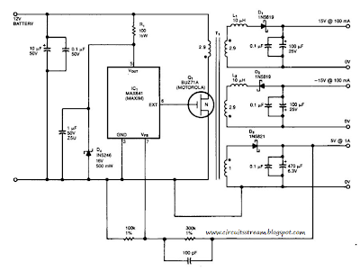
Simple 15V And 5V Car Battery Supply Circuit Diagram
This is a Simple 15V And 5V Car Battery Supply Circuit Diagram. In this circuit use IC1 is a switching regulator that generates a 45-kHz signal that drives the gate of MOSFET Ql. Dl, D2, and D3 are Schottky diodes. The 5-V output is sensed as a reference; feedback to the chip turns off the gate signal to Ql if the voltage rises above 5 V.
Tl has Trifilar windings that assume about 2% regulation for a 10-to 100-mA load change on the ± 15-V supplies. R1/D4 provide over-voltage protection. Tl has a primary inductance of about 21 . Core size should allow 4-A peak currents. The turn ratios are IIV2 turns each for the 15-V supplies, ll1/2 turns for the primary, and four turns for the 5-V secondary. The efficiency is about 75%.
Simple 15V And 5V Car Battery Supply Circuit Diagram
Subscribe to:
Posts (Atom)