Thursday, January 9, 2014
Browse »
home»
15v
»
5v
»
and
»
battery
»
car
»
circuit
»
diagram
»
simple
»
supply
»
Simple 15V And 5V Car Battery Supply Circuit Diagram

Simple 15V And 5V Car Battery Supply Circuit Diagram
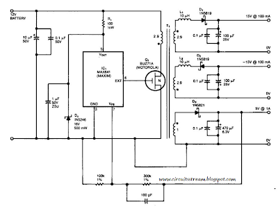
This is a Simple 15V And 5V Car Battery Supply Circuit Diagram. In this circuit use IC1 is a switching regulator that generates a 45-kHz signal that drives the gate of MOSFET Ql. Dl, D2, and D3 are Schottky diodes. The 5-V output is sensed as a reference; feedback to the chip turns off the gate signal to Ql if the voltage rises above 5 V.
Tl has Trifilar windings that assume about 2% regulation for a 10-to 100-mA load change on the ± 15-V supplies. R1/D4 provide over-voltage protection. Tl has a primary inductance of about 21 . Core size should allow 4-A peak currents. The turn ratios are IIV2 turns each for the 15-V supplies, ll1/2 turns for the primary, and four turns for the 5-V secondary. The efficiency is about 75%.
Simple 15V And 5V Car Battery Supply Circuit Diagram

Related to Simple 15V And 5V Car Battery Supply Circuit Diagram
15v, 5v, and, battery, car, circuit, diagram, simple, supply
Subscribe to:
Post Comments (Atom)
No comments:
Post a Comment
Note: Only a member of this blog may post a comment.