Showing posts with label with. Show all posts
Showing posts with label with. Show all posts
Wednesday, December 18, 2013
12V Lead Acid Battery Charger with Indicator
Some of you might wonder why a charger is needed at all, to charge a 12 Volt battery from a 12 Volt source! Well, firstly the "12 Volt" source will typically vary anywhere from 11 Volt to 15 Volt, and then a battery needs a controlled charge current and voltage, which cannot result from connecting it directly to a voltage source. The charger described here is intended for charging small 12 Volt lead acid batteries, such as the gelled or AGM batteries of capacities between about 2 and 10 Ah, using a cars electrical system as power source, regardless of whether the car engine is running or not.

I built this charger many years ago, I think I was still in school back then. On request of a reader of my web site, Im publishing it now, despite being a rather crude circuit. It works, it is uncritical to build, and uses only easy-to-find parts, so it has something in its favor. The downside is mainly the low efficiency: This charger wastes about as much power as it puts into the battery. The charger consists of two stages: The first is a capacitive voltage doubler, which uses a 555 timer IC driving a pair of transistors connected as emitter followers, which in turn drive the voltage doubler proper.

The doubler has power resistors built in, which limit the charging current. The second stage is a voltage regulator, using a 7815 regulator IC. Its output is applied to the battery via a diode, which prevents reverse current and also lowers the voltage a bit. The resulting charge voltage is about 14.4V, which is fine for charging a gelled or AGM battery to full charge, but is too high as a trickle charger, so dont leave this charger permanently connected to a battery.
If you would like to do just that, then add a second diode in series with D3! There is a LED connected as a charge indicator. It will light when the charge current is higher than about 150mA. The maximum charge current will be roughly 400mA. There is an auxiliary output, that provides about 20V at no load (depending on input voltage), and comes down as the load increases. I included this for charging 12V, 4Ah NiCd packs, which require just a limited current but not a limited voltage for charging.

Note that if the charge output is short-circuited, the over-current protection of U2 will kick in, but the current is still high enough to damage the diodes, if it lasts. So, dont short the output! If instead you short the auxiliary output, the fuse should blow. I built this charger into a little homemade aluminum sheet enclosure, using dead-bug construction style. Not very tidy, but it works. Note the long leads on the power resistors. They are necessary, because with shorter leads the resistors will unsolder themselves, as they get pretty hot! The transistors and the regulator IC are bolted to the case, which serves as heat sink. The transistors dont heat up very much, but the IC does.
Readmore...

I built this charger many years ago, I think I was still in school back then. On request of a reader of my web site, Im publishing it now, despite being a rather crude circuit. It works, it is uncritical to build, and uses only easy-to-find parts, so it has something in its favor. The downside is mainly the low efficiency: This charger wastes about as much power as it puts into the battery. The charger consists of two stages: The first is a capacitive voltage doubler, which uses a 555 timer IC driving a pair of transistors connected as emitter followers, which in turn drive the voltage doubler proper.

The doubler has power resistors built in, which limit the charging current. The second stage is a voltage regulator, using a 7815 regulator IC. Its output is applied to the battery via a diode, which prevents reverse current and also lowers the voltage a bit. The resulting charge voltage is about 14.4V, which is fine for charging a gelled or AGM battery to full charge, but is too high as a trickle charger, so dont leave this charger permanently connected to a battery.
If you would like to do just that, then add a second diode in series with D3! There is a LED connected as a charge indicator. It will light when the charge current is higher than about 150mA. The maximum charge current will be roughly 400mA. There is an auxiliary output, that provides about 20V at no load (depending on input voltage), and comes down as the load increases. I included this for charging 12V, 4Ah NiCd packs, which require just a limited current but not a limited voltage for charging.

Note that if the charge output is short-circuited, the over-current protection of U2 will kick in, but the current is still high enough to damage the diodes, if it lasts. So, dont short the output! If instead you short the auxiliary output, the fuse should blow. I built this charger into a little homemade aluminum sheet enclosure, using dead-bug construction style. Not very tidy, but it works. Note the long leads on the power resistors. They are necessary, because with shorter leads the resistors will unsolder themselves, as they get pretty hot! The transistors and the regulator IC are bolted to the case, which serves as heat sink. The transistors dont heat up very much, but the IC does.
Source: Homo Ludens

Tuesday, December 17, 2013
Wideband Wien Oscillator with Single Gang Pot
This Wien bridge oscillator (after Max Wien, 1866–1938) produces a low-distortion sine wave of constant amplitude, from about 15 Hz to 150 kHz. It requires just four opamps and will work off a single 9-volt battery. Also, unlike most Wien bridge oscillators, it does not require a dual-gang potentiometer for tuning. Op amp IC2b provides an artificial ground so that the circuit will operate from a unipolar supply (9 V battery or power pack). IC2a is the main amplifier for the oscillator. The frequency range is divided into four decades by 2-pole, 4-way rotary switch SW1.
Only one arm of the Wien network is varied, but the change in positive feedback that would normally result is compensated for by IC1b, which works to bootstrap R2, thereby changing the negative feedback enough to maintain oscillation. A linear change in the resistance of the tuning pot results in a roughly logarithmic change in frequency. To get a more conventional linear change a log-taper pot is used wired so that rotating the knob anticlockwise causes frequency to increase.

You could use an anti-log pot the other way around if you prefer, but these things are notoriously hard to find. IC1A is an integrator that monitors the amplitude of the output signal and drives an LED (D2). This must be mounted facing the LDR (light dependent resistor) and shielded from ambient light (for example, with a piece of heat-shrink tubing). IC1a is then able to control the gain of IC2a so that oscillation is maintained with minimum distortion.
The maximum output amplitude of the generator is about 2 Vp-p when the LED and LDR are mounted as close as possible. Distortion is less than 0.5 % in the lowest range, and too low for the author to measure in the higher ranges. Any LDR should work, provided its dark resistance is greater than 100 kO. If you do not have an LDR with such high resistance, try increasing R5 until oscillation starts. Breadboarded prototypes of the circuit were built by the author using dual and quad opamp packages, and both work equally well.
Author: Merlin Blencowe (Elektor)
Resistors:
R1,R2,R3,R6,R10,R11 = 10kO
R7 = 100kO
R4,R9,R12 = 100O
R5 = 12kO
R8 = 1kO
P1,P2 = 10kO potentiometer, logarithmic law
R13 = LDR, R(dark) >100kO, e.g. Excelitas Tech type
VT90N1 (Newark/Farnell # 2568243)
Capacitors:
C1,C5 = 1µF solid
C2,C6 = 100nF
C3,C7 = 10nF
C4,C8 = 1nF
C9-C12 = 47µF 16V, electrolytic, radial
Semiconductors:
D1,D2,D3 = 1N4148
D4 = LED, red, 5mm
IC1,IC2 = TL072ACP
Miscellaneous:
SW1 = 2-pole 4-position rotary switch, C&K Compo-
nents type RTAP42S04WFLSS
K1,K2 = PCB terminal block, 5mm pitch
Readmore...
Only one arm of the Wien network is varied, but the change in positive feedback that would normally result is compensated for by IC1b, which works to bootstrap R2, thereby changing the negative feedback enough to maintain oscillation. A linear change in the resistance of the tuning pot results in a roughly logarithmic change in frequency. To get a more conventional linear change a log-taper pot is used wired so that rotating the knob anticlockwise causes frequency to increase.

You could use an anti-log pot the other way around if you prefer, but these things are notoriously hard to find. IC1A is an integrator that monitors the amplitude of the output signal and drives an LED (D2). This must be mounted facing the LDR (light dependent resistor) and shielded from ambient light (for example, with a piece of heat-shrink tubing). IC1a is then able to control the gain of IC2a so that oscillation is maintained with minimum distortion.
The maximum output amplitude of the generator is about 2 Vp-p when the LED and LDR are mounted as close as possible. Distortion is less than 0.5 % in the lowest range, and too low for the author to measure in the higher ranges. Any LDR should work, provided its dark resistance is greater than 100 kO. If you do not have an LDR with such high resistance, try increasing R5 until oscillation starts. Breadboarded prototypes of the circuit were built by the author using dual and quad opamp packages, and both work equally well.
Author: Merlin Blencowe (Elektor)
Resistors:
R1,R2,R3,R6,R10,R11 = 10kO
R7 = 100kO
R4,R9,R12 = 100O
R5 = 12kO
R8 = 1kO
P1,P2 = 10kO potentiometer, logarithmic law
R13 = LDR, R(dark) >100kO, e.g. Excelitas Tech type
VT90N1 (Newark/Farnell # 2568243)
Capacitors:
C1,C5 = 1µF solid
C2,C6 = 100nF
C3,C7 = 10nF
C4,C8 = 1nF
C9-C12 = 47µF 16V, electrolytic, radial
Semiconductors:
D1,D2,D3 = 1N4148
D4 = LED, red, 5mm
IC1,IC2 = TL072ACP
Miscellaneous:
SW1 = 2-pole 4-position rotary switch, C&K Compo-
nents type RTAP42S04WFLSS
K1,K2 = PCB terminal block, 5mm pitch
Thursday, September 12, 2013
Ethernet Shield with ENC28J60
One of the most interesting shield that you can mount on the Arduino platform is certainly the ethernet shield, because enable numerous networking applications such as remote control of systems and users, web access and publication of data, and more yet, the simplicity of finding and integrating open-source libraries on Arduino IDE does the rest.

Wednesday, September 4, 2013
Build an op amp with three Discrete Transistors
You can use three discrete transistors to build an operational amplifier with an open-loop gain greater than 1 million (Figure 1). You bias the output at approximately one-half the supply voltage using the combined voltage drops across zener diode D1, the emitter-base voltage of input transistor Q1, and the 1V drop across 1-MΩ feed-back resistor R2.
Resistor R3 and capacitor C1 form a compensation network that prevents the circuit from oscillating. The values in the figure still provide a good square-wave response. The ratio of R2 to R1 determines the inverting gain, which is −10 in this example.
You can configure this op amp as an active filter or as an oscillator. It drives a load of 1 kΩ. The square-wave response is good at 10 kHz, and the output reduces by 3 dB at 50 kHz. Set the 50-Hz low-frequency response with the values of the input and the output capacitors. You can raise the high-frequency response by using faster transistors and doing careful layout. Link
 | |
| Figure 1. | This ac-coupled inverting op amp has an open-loop gain of 1 million. R1 and R2 set a closed-loop gain of −10. |
Resistor R3 and capacitor C1 form a compensation network that prevents the circuit from oscillating. The values in the figure still provide a good square-wave response. The ratio of R2 to R1 determines the inverting gain, which is −10 in this example.
You can configure this op amp as an active filter or as an oscillator. It drives a load of 1 kΩ. The square-wave response is good at 10 kHz, and the output reduces by 3 dB at 50 kHz. Set the 50-Hz low-frequency response with the values of the input and the output capacitors. You can raise the high-frequency response by using faster transistors and doing careful layout. Link
Monday, September 2, 2013
Infrared Receiver with Status LED
This is the latest version of the Improved Infrared Receiver with Status LED which can control any desktop PC with an ordinary remote control. The project comes along with a small PCB in order to save space. It connects to the serial port as stated in the schematic and uses the freeware Girder (www.girder.nl) software together with Igor’s Plugin (www.cesko.host.sk/girderplugin.htm) to send commands to the PC. The potential uses of this device are countless (control MP3 players, CD and DVD players, radio and TV cards, even move the mouse cursor and shutdown the computer remotely !). Again, note that any ordinary remote control can be used by training Girder to learn its signals !
Project Image

Parts list:
R1 3.3K 1/4W
R2 10K 1/4W
R3 100K 1/4W
R4 10K 1/4W
R5 100K 1/4W
R6 220 1/4W
D1 1N4148
D2 LED 3mm
C1 4.7uF/16V Electrolytic
Q1 BC548
Q2 BC558
IC1 78L05
IC2 TSOP 1736/38/40 (may work with Siemens SFH506xx receivers also)
E1 CR2032 3V battery + PCB base
Misc Three pins to connect the serial cable (optional)
The improvements of this project compared to the ones already published in the internet is that it uses regulated power for the infrared receiver module (TSOP 17xx), has improved sensitivity (worked at a distance of about 10 m), and features a status led which is powered by an external battery source and is driven by two transistors. Upon signal reception, the led blinks to provide a visual feedback to the sender.
Infrared Receiver with Status LED Circuit Daigram
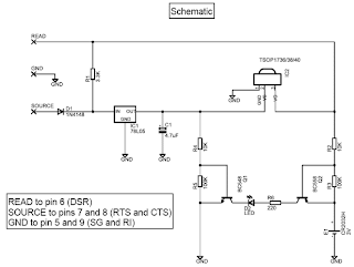
The PCB features narrow tracks (16 mil) so special care should be paid during the construction. The 4.7 uF capacitor is bent towards the board in order to save height if the circuit is to be placed in a small plastic box.

The Girder software for this project was preferred because it is first of all freeware, it is stable and customizable, features a large number of commands and supports user plugins. It is a bit difficult to learn at first, but after a while it deploys a great number of possibilities that other programs (even commercial ones) lack. Nevertheless, with the right corrections (pin changes) this project may be used with other software (WinLIRC, IRAssistant, Miriam, PCRemote) but no such testing has been carried out yet. This is maybe a good point for further search.
ΙR Reciever Pin Numer
Source 7 (RTS)
Ground 5 (GND)
Read 1 (DCD)
Project Image
Parts list:
R1 3.3K 1/4W
R2 10K 1/4W
R3 100K 1/4W
R4 10K 1/4W
R5 100K 1/4W
R6 220 1/4W
D1 1N4148
D2 LED 3mm
C1 4.7uF/16V Electrolytic
Q1 BC548
Q2 BC558
IC1 78L05
IC2 TSOP 1736/38/40 (may work with Siemens SFH506xx receivers also)
E1 CR2032 3V battery + PCB base
Misc Three pins to connect the serial cable (optional)
The improvements of this project compared to the ones already published in the internet is that it uses regulated power for the infrared receiver module (TSOP 17xx), has improved sensitivity (worked at a distance of about 10 m), and features a status led which is powered by an external battery source and is driven by two transistors. Upon signal reception, the led blinks to provide a visual feedback to the sender.
Infrared Receiver with Status LED Circuit Daigram
The PCB features narrow tracks (16 mil) so special care should be paid during the construction. The 4.7 uF capacitor is bent towards the board in order to save height if the circuit is to be placed in a small plastic box.
The Girder software for this project was preferred because it is first of all freeware, it is stable and customizable, features a large number of commands and supports user plugins. It is a bit difficult to learn at first, but after a while it deploys a great number of possibilities that other programs (even commercial ones) lack. Nevertheless, with the right corrections (pin changes) this project may be used with other software (WinLIRC, IRAssistant, Miriam, PCRemote) but no such testing has been carried out yet. This is maybe a good point for further search.
ΙR Reciever Pin Numer
Source 7 (RTS)
Ground 5 (GND)
Read 1 (DCD)
Sunday, September 1, 2013
Headphones with Noise Canceling Feature
The project produces noise-canceling headphones which allow the background noise to be minimized while listening to music.
To keep the microphone signals in phase, the project consists of a phase switch that amplifies the background sound making it lend itself to several other interesting functions. There are three op-amp circuits that make up the electronics where each is built around one half of a dual op-amp NE5532. The op-amp is used by each circuit in a different configuration. A non-inverting pre-amp is done by the first circuit, a unity-gain phase-inverter by the second, and an inverting headphone amplifier by the third. The circuit is actually two circuits side-by-side since the noise-canceling headphone is a stereo device.

All inverted sounds played back through the headphones cancel out the original sounds, leaving nothing but silence since the noise-canceling headphone is a simple phase-inverting amplifier. For different situations, the amount of canceling can be adjusted. The circuit is relatively simple and can be easily assembled on a perfboard with two parts containing the construction of electronics and modifying a pair of headphones. The microphones are mounted on earpieces of the headphones with a dab of silicon sealant.
To keep the microphone signals in phase, the project consists of a phase switch that amplifies the background sound making it lend itself to several other interesting functions. There are three op-amp circuits that make up the electronics where each is built around one half of a dual op-amp NE5532. The op-amp is used by each circuit in a different configuration. A non-inverting pre-amp is done by the first circuit, a unity-gain phase-inverter by the second, and an inverting headphone amplifier by the third. The circuit is actually two circuits side-by-side since the noise-canceling headphone is a stereo device.

All inverted sounds played back through the headphones cancel out the original sounds, leaving nothing but silence since the noise-canceling headphone is a simple phase-inverting amplifier. For different situations, the amount of canceling can be adjusted. The circuit is relatively simple and can be easily assembled on a perfboard with two parts containing the construction of electronics and modifying a pair of headphones. The microphones are mounted on earpieces of the headphones with a dab of silicon sealant.
Subscribe to:
Posts (Atom)