Monday, October 7, 2013
Condenser Mic Audio Amplifier

BEL1895 is a monolithic audio power amplifier IC designed specifically for sensitive AM radio applications that delivers 1 watt into 4 ohms at 6V power supply voltage. It exhibits low distortion and noise and operates over 3V-9V supply voltage, which makes it ideal for battery operation. A turn-on pop reduction circuit prevents thud when the power supply is switched on. Coupling capacitor C7 determines low-frequency response of the amplifier. Capacitor C9 acts as the ripple-rejection filter.
Capacitor C13 couples the output available at pin 1 to the loudspeaker. R15-C13 combination acts as the damping circuit for output oscillations. Capacitor C12 provides the boot strapping function. This circuit is suitable for low-power HAM radio transmitters to supply the necessary audio power for modulation. With simple modifications it can also be used in intercom circuits.

Sunday, September 22, 2013
USB Powered Audio Power Amplifier Circuit Diagram
This circuit of multimedia speakers for PCs has single-chip-based design, low-voltage power supply, compatibility with USB power, easy heat-sinking, low cost, high flexibility and wide temperature tolerance. At the heart of the circuit is IC TDA2822M. This IC is, in fact, mono-lithic type in 8-lead mini DIP package. It is intended for use as a dual audio power amplifier in battery-powered sound players. Specifications of TDA2822M are low quiescent current, low crossover distortion, supply voltage down to 1.8 volts and minimum output power of around 450 mW/channel with 4-ohm loudspeaker at 5V DC supply input.
An ideal power amplifier can be simply defined as a circuit that can deliver audio power into external loads without generating significant signal distortion and without consuming excessive quiescent current. This circuit is powered by 5V DC supply available from the USB port of the PC. When power switch S1 is flipped to ‘on’ position, 5V power supply is extended to the circuit and power-indicator red LED1 lights up instantly. Resistor R1 is a current surge limiter and capacitors C1 and C4 act as buffers. Working of the circuit is simple. Audio signals from the PC audio socket/headphone socket are fed to the amplifier circuit through components R2 and C2 (left channel), and R3 and C3 (right channel).
Circuit diagram:

USB Powered Audio Power Amplifier Circuit Diagram
Potmeter VR1 works as the volume controller for left (L) channel and potmeter VR2 works for right (R) channel. Pin 7 of TDA2822M receives the left-channel sound signals and pin 6 receives the right-channel signals through VR1 and VR2, respectively. Ampl i f ied signals for driving the left and right loudspeakers are available at pins 1 and 3 of IC1, respectively. Components R5 and C8, and R6 and C10 form the traditional zobel network. Assemble the circuit on a medium-size, general-purpose PCB and enclose in a suitable cabinet. It is advisable to use a socket for IC TDA2822M. The external connections should be made using suitably screened wires for better result.
Author: T.K. Hareendran - Copyright: EFY Mag
Tuesday, September 10, 2013
3khz Low Pass Filter and Audio Amplifier Circuit Diagram

Wednesday, September 4, 2013
200 Watt Audio Amplifier
200 Watt Audio Amplifier Circuit Diagram
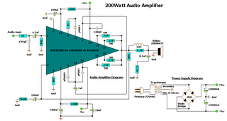
Notes :
Output Power : 200Watts
Load Resistance : 8ohms
Input impedance : 55K
Maximum supply voltage : (+95v)-0-(-95v)
Recommended supply voltage : (+66v)-0-(-66v)
Friday, August 30, 2013
32W Hi Fi Audio Amplifier Using TDA2050
32W Hi-Fi Audio Amplifier Circuit Diagram


The TDA 2050 is a monolithic integrated circuit in Pentawatt package, intended for use as an audio class AB audio amplifier. Thanks to its high power capability the TDA2050 is able to provide up to 35W true rms power into 4 ohm load @ THD =10%, VS = ±18V, f = 1KHz and up to 32W into 8ohm load @ THD = 10%, VS = ±22V, f = 1KHz. Moreover, the TDA 2050 delivers typically 50W music power into 4 ohm load over 1 sec at VS=22.5V, f = 1KHz.
The high power and very low harmonic and crossover distortion (THD = 0.05% typ, @ VS = ±22V, PO = 0.1 to 15W, RL=8ohm, f = 100Hz to 15KHz) make the device most suitable for both HiFi and high class TV sets.