Sunday, December 22, 2013
1000 watt power inverter circuit diagram
Circuit Diagram | 1000 watt power inverter
 |
| Fig:Schematic diagram of 1000 watt power inverter |
How to parallel MOSFETs | 1000 watt power inverter

Source: http://www3.telus.net/chemelec/Projects/Inverter/Mosfet-Inverter.htm

Sunday, October 6, 2013
0 5 WATT MINI AMPLIFIER TDA1015T ELECTRONIC DIAGRAM

Chances are youll want this amplifier portable. Batteries do the trick fine, but you wont get much power out of a couple of 1.5V cells. Unfortunately the size of a decent amount of battery power will mean that the overall size of this amp will be much bigger and for that there are more benefits to be had using a device like the TDA7052 or TDA2822 for stereo.
Quick ref data of TDA1015T Chip
- Supply voltage range: 3,6 to 12 V
- Peak output current: 1 A
- Output power: 0,5 W
- Voltage gain power amplifier: 29 dB
- Voltage gain preamplifier: 23 dB
- Total quiescent current: 22 mA
- Operating ambient temperature range: -25 to +150 °C
- Storage temperature range: -55 to + 150 °C
Monday, September 23, 2013
22 Watt Car Subwoofer Amplifier
22W into 4 Ohm power amplifier, Variable Low Pass Frequency: 70 – 150Hz
This unit is intended to be connected to an existing car stereo amplifier, adding the often required extra "punch" to the music by driving a subwoofer. As very low frequencies are omnidirectional, a single amplifier is necessary to drive this dedicated loudspeaker. The power amplifier used is a good and cheap BTL (Bridge Tied Load) 13 pin IC made by Philips (now NXP Semiconductors) requiring a very low parts count and capable of delivering about 22W into a 4 Ohm load at the standard car battery voltage of 14.4V.
Circuit diagram:
 22 Watt Car Subwoofer Amplifier Circuit Diagram
Parts:
P1_____________10K Log Potentiometer
P2_____________22K Dual gang Linear Potentiometer
R1,R4___________1K 1/4W Resistors
R2,R3,R5,R6____10K 1/4W Resistors
R7,R8_________100K 1/4W Resistors
R9,R10,R13_____47K 1/4W Resistors
R11,R12________15K 1/4W Resistors
R14,R15,R17____47K 1/4W Resistors
R16_____________6K8 1/4W Resistor
R18_____________1K5 1/4W Resistor
C1,C2,C3,C6_____4µ7 25V Electrolytic Capacitors
C4,C5__________68nF 63V Polyester Capacitors
C7_____________33nF 63V Polyester Capacitor
C8,C9_________220µF 25V Electrolytic Capacitors
C10___________470nF 63V Polyester Capacitor
C11___________100nF 63V Polyester Capacitor
C12__________2200µF 25V Electrolytic Capacitor
D1______________LED any color and type
Q1,Q2_________BC547 45V 100mA NPN Transistors
IC1___________TL072 Dual BIFET Op-Amp
IC2_________TDA1516BQ 24W BTL Car Radio Power Amplifier IC
SW1____________DPDT toggle or slide Switch
SW2____________SPST toggle or slide Switch capable of withstanding a current of at least 3A
J1,J2__________RCA audio input sockets
SPKR___________4 Ohm Woofer or two 8 Ohm Woofers wired in parallel
The stereo signals coming from the line outputs of the car radio amplifier are mixed at the input and, after the Level Control, the signal enters the buffer IC1A and can be phase reversed by means of SW1. This control can be useful to allow the subwoofer to be in phase with the loudspeakers of the existing car radio. Then, a 12dB/octave variable frequency Low Pass filter built around IC1B, Q1 and related components follows, allowing to adjust precisely the low pass frequency from 70 to 150Hz. Q2, R17 and C9 form a simple dc voltage stabilizer for the input and filter circuitry, useful to avoid positive rail interaction from the power amplifier to low level sections.
Notes:
- IC2 must be mounted on a suitable finned heatsink
- Due to the long time constant set by R17 and C9 in the dc voltage stabilizer, the whole amplifier will become fully operative about 15 - 30 sec. after switch-on.
Technical data:
Output power (1KHz sinewave):
22W RMS into 4 Ohms at 14.4V supply
Sensitivity:
250mV input for full output
Frequency response:
20Hz to 70Hz -3dB with the cursor of P2 fully rotated towards R12
20Hz to 150Hz -3dB with the cursor of P2 fully rotated towards R11
Total harmonic distortion:
17W RMS: 0.5% 22W RMS: 10%
Source : www.redcircuits.com
Thursday, September 5, 2013
1000 Watt Power Inverter Schematic
1000 watt power inverter Circuit Diagram


Wednesday, September 4, 2013
200 Watt Audio Amplifier
200 Watt Audio Amplifier Circuit Diagram
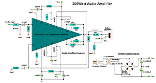
Notes :
Output Power : 200Watts
Load Resistance : 8ohms
Input impedance : 55K
Maximum supply voltage : (+95v)-0-(-95v)
Recommended supply voltage : (+66v)-0-(-66v)