Showing posts with label infrared. Show all posts
Showing posts with label infrared. Show all posts
Wednesday, December 25, 2013
DIY Infrared Radar System
Chris from PyroElectro.com has a great article about a do-it-yourself radar system build with PIC18F452. It’s a great hobby project although the schematic is very complicated. This project uses three main devices to create the personal radar system. The IR Range sensor gives output, the pic microcontroller processes it and then displays the output on the led array.
DIY Infrared Radar Circuit Schematic

The goal of this project is to create a working ir radar system. The system will only be required to measure close proximity at an angle of 90 degrees as seen in the example above. The range of system is roughly 4-30cm, 20-150cm & 1m-5.5m depending upon which sensor you choose to use. [Link]DIY Infrared Radar Circuit Schematic

Saturday, October 5, 2013
Infrared Remote Receiver Has Four Outputs
This circuit enables any infrared (IR) remote control to control the outputs of a 4017 decade counter. Its quite simple really and uses a 3-terminal IR receiver (IRD1) to pick up infrared signals from the transmitter. IRD1s output is then coupled to NPN transistor Q1 via a 220nF capacitor. Transistor Q1 functions as a common-emitter amplifier with a gain of about 20, as set by the ratio of its 10kO collector resistor to its 470O emitter resistor. Q1 in turn triggers IC1, a 4047 monostable which in turn clocks a 4017 decade counter (IC2).

Basically, IC1 provides a clock pulse to IC2 each time a remote control button is pressed. If you dont wish to use all 10 outputs from IC2, simply connect the first unused output to pin 15 (MR). In this case, only the first four outputs (O0-O3) of the counter are used and so the O4 output is connected to pin 15 to reset the counter on the fifth button press. Power for the circuit is derived from the mains via a transformer and bridge rectifier which produces about 15-27V DC. This is then fed to 3-terminal regulators REG1 & REG2 to derive +12V and +5V supply rails.
Readmore...

Basically, IC1 provides a clock pulse to IC2 each time a remote control button is pressed. If you dont wish to use all 10 outputs from IC2, simply connect the first unused output to pin 15 (MR). In this case, only the first four outputs (O0-O3) of the counter are used and so the O4 output is connected to pin 15 to reset the counter on the fifth button press. Power for the circuit is derived from the mains via a transformer and bridge rectifier which produces about 15-27V DC. This is then fed to 3-terminal regulators REG1 & REG2 to derive +12V and +5V supply rails.
Monday, September 2, 2013
Infrared Receiver with Status LED
This is the latest version of the Improved Infrared Receiver with Status LED which can control any desktop PC with an ordinary remote control. The project comes along with a small PCB in order to save space. It connects to the serial port as stated in the schematic and uses the freeware Girder (www.girder.nl) software together with Igor’s Plugin (www.cesko.host.sk/girderplugin.htm) to send commands to the PC. The potential uses of this device are countless (control MP3 players, CD and DVD players, radio and TV cards, even move the mouse cursor and shutdown the computer remotely !). Again, note that any ordinary remote control can be used by training Girder to learn its signals !
Project Image

Parts list:
R1 3.3K 1/4W
R2 10K 1/4W
R3 100K 1/4W
R4 10K 1/4W
R5 100K 1/4W
R6 220 1/4W
D1 1N4148
D2 LED 3mm
C1 4.7uF/16V Electrolytic
Q1 BC548
Q2 BC558
IC1 78L05
IC2 TSOP 1736/38/40 (may work with Siemens SFH506xx receivers also)
E1 CR2032 3V battery + PCB base
Misc Three pins to connect the serial cable (optional)
The improvements of this project compared to the ones already published in the internet is that it uses regulated power for the infrared receiver module (TSOP 17xx), has improved sensitivity (worked at a distance of about 10 m), and features a status led which is powered by an external battery source and is driven by two transistors. Upon signal reception, the led blinks to provide a visual feedback to the sender.
Infrared Receiver with Status LED Circuit Daigram
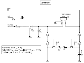
The PCB features narrow tracks (16 mil) so special care should be paid during the construction. The 4.7 uF capacitor is bent towards the board in order to save height if the circuit is to be placed in a small plastic box.

The Girder software for this project was preferred because it is first of all freeware, it is stable and customizable, features a large number of commands and supports user plugins. It is a bit difficult to learn at first, but after a while it deploys a great number of possibilities that other programs (even commercial ones) lack. Nevertheless, with the right corrections (pin changes) this project may be used with other software (WinLIRC, IRAssistant, Miriam, PCRemote) but no such testing has been carried out yet. This is maybe a good point for further search.
ΙR Reciever Pin Numer
Source 7 (RTS)
Ground 5 (GND)
Read 1 (DCD)
Project Image
Parts list:
R1 3.3K 1/4W
R2 10K 1/4W
R3 100K 1/4W
R4 10K 1/4W
R5 100K 1/4W
R6 220 1/4W
D1 1N4148
D2 LED 3mm
C1 4.7uF/16V Electrolytic
Q1 BC548
Q2 BC558
IC1 78L05
IC2 TSOP 1736/38/40 (may work with Siemens SFH506xx receivers also)
E1 CR2032 3V battery + PCB base
Misc Three pins to connect the serial cable (optional)
The improvements of this project compared to the ones already published in the internet is that it uses regulated power for the infrared receiver module (TSOP 17xx), has improved sensitivity (worked at a distance of about 10 m), and features a status led which is powered by an external battery source and is driven by two transistors. Upon signal reception, the led blinks to provide a visual feedback to the sender.
Infrared Receiver with Status LED Circuit Daigram
The PCB features narrow tracks (16 mil) so special care should be paid during the construction. The 4.7 uF capacitor is bent towards the board in order to save height if the circuit is to be placed in a small plastic box.
The Girder software for this project was preferred because it is first of all freeware, it is stable and customizable, features a large number of commands and supports user plugins. It is a bit difficult to learn at first, but after a while it deploys a great number of possibilities that other programs (even commercial ones) lack. Nevertheless, with the right corrections (pin changes) this project may be used with other software (WinLIRC, IRAssistant, Miriam, PCRemote) but no such testing has been carried out yet. This is maybe a good point for further search.
ΙR Reciever Pin Numer
Source 7 (RTS)
Ground 5 (GND)
Read 1 (DCD)
Subscribe to:
Posts (Atom)