Showing posts with label light. Show all posts
Showing posts with label light. Show all posts
Friday, December 20, 2013
Warning Light and Marker Light Circuit Diagram
This is a Warning Light and Marker Light Circuit Diagram. A flashing light of high brightness and short duty cycle is often desired to provide maximum visibility and battery life. This necessitates using an output transistor, which can supply the cold filament surge current of the lamp while maintaining a low saturation voltage. The oscillation period and flash duration are determined in the feedback loop, while the use of a photo transistor sensor minimizes sensitivity variations.
Warning Light and Marker Light Circuit Diagram

Friday, September 27, 2013
Direction Sensitive Light Barrier
With two light barriers closely positioned one after the other it is possible to establish in which direction they have been crossed. If, for example, you place it at the entrance of the toilet then you can use it to control the lights: on when entering and off when leaving the room. The circuit for this has many similarities with the modulated light barrier appearing else-where in this Summer Circuits issue. There are two ways to position the light barriers, namely a completely duplicated installation in opposing directions (this to prevent mutual interference) and a version with one IR transmitter and two receivers.

Both types of installation are shown here, which one is most suitable depends on the actual application. When used in a doorway, one transmitter is sufficient if the receivers are placed about 5 cm apart. With a wider passage, an installation with two separate IR-transmitters is a better solution. This circuit has a range of several meters, even if the sun shines directly on the receiver! We use the exact same IR-transmitter(s) as for the modulated light barrier. For the installation with two separate IR-transmitters it is sufficient to duplicate R6, T1, D1, C3 and R7 from the circuit of the modulated light barrier.

Output OUT (pin 3) of IC2 can drive two of these IR-drivers without any difficulty. The receivers are slightly different than those of the modulated light barrier and the circuit is the same for both types of installation. We again use the TSOP1736, which is sensitive to IR-light that is modulated at a frequency of 36 kHz. D2, R8 and C4 ensure that the received pulses from IC3 at the output of IC5a result in a ‘1’ when the beam is not interrupted. When the beam is interrupted this output will become a ‘0’ within about 1 ms.
In the same way IC5b generates a ‘0’ when IC4 stops receiving IR-light. The 4013 CMOS-IC used here contains two D-flipflops, of which we use only one. The instant that light barrier 2 (IC4) is unblocked again, is used to clock the state of light barrier 1 (IC3) through to output Q1. This signal drives the relay via T2, which operates the light in the room. The circuit therefore turns the light on or off the moment that light barrier 1 is uninterrupted.
Readmore...
Both types of installation are shown here, which one is most suitable depends on the actual application. When used in a doorway, one transmitter is sufficient if the receivers are placed about 5 cm apart. With a wider passage, an installation with two separate IR-transmitters is a better solution. This circuit has a range of several meters, even if the sun shines directly on the receiver! We use the exact same IR-transmitter(s) as for the modulated light barrier. For the installation with two separate IR-transmitters it is sufficient to duplicate R6, T1, D1, C3 and R7 from the circuit of the modulated light barrier.
Output OUT (pin 3) of IC2 can drive two of these IR-drivers without any difficulty. The receivers are slightly different than those of the modulated light barrier and the circuit is the same for both types of installation. We again use the TSOP1736, which is sensitive to IR-light that is modulated at a frequency of 36 kHz. D2, R8 and C4 ensure that the received pulses from IC3 at the output of IC5a result in a ‘1’ when the beam is not interrupted. When the beam is interrupted this output will become a ‘0’ within about 1 ms.
In the same way IC5b generates a ‘0’ when IC4 stops receiving IR-light. The 4013 CMOS-IC used here contains two D-flipflops, of which we use only one. The instant that light barrier 2 (IC4) is unblocked again, is used to clock the state of light barrier 1 (IC3) through to output Q1. This signal drives the relay via T2, which operates the light in the room. The circuit therefore turns the light on or off the moment that light barrier 1 is uninterrupted.
Switch Timer Circuit For Bathroom Light
This 9-minute timer switch can be used to control the light in a toilet or bathroom. The timer is started by pushing S1 and stopped by pushing S1 again. If you forget to turn it off, the controlled light will go off after nine minutes. If you need the light on continuously non-stop, you need to press S1 (turn on) and then S2 (cancellation of timer) within 9 minutes and in this case the light will be on until you switch it off with S1.
Circuit diagram:

IC1 is a is 4013 dual flip-flop. Flip flop IC1a is toggled on and off by switch S1 and it controls the relay which is switched by FET Q2. IC1a controls IC1b which is connected as an RS flipflop to enable or disable IC2, a 4060 oscillator/divider. This has its timing interval set by the components at its pins 9, 10 & 11. The relay should have 250VAC mains-rated contacts and these are connected in parallel with an existing wall switch.
Author: Rasim Kucalovic - Copyright: Silicon Chip Electronics
Tuesday, September 24, 2013
Automatic Light Dimmer
In many cases, the dimmer presented here may be built into a wall-mounted box containing the light switch. It is intended for use with 240 V incandescent lamps only. When it is fitted, and the light is switched on, the lamp does not come on fully for about 400 ms (which is not noticeable). When the light is switched off, it stays on unchanged for about 20 s, and then goes out gradually. This has the advantage that it is not immediately dark when the light is switched off. When light switch S1 is turned on, capacitor C2 is charged via R1, C1 and bridge rectifier D1–D4. Zener diode D5 limits the potential across C2 to about 15 V. After a short while, diode D6 lights, whereupon a potential difference ensues across light sensitive resistor R3, which is sufficient to trigger triac Tr1.

The light then comes on. When the light switch is turned off, C2 is discharged via P1, R2 and D6. When the potential across C2 drops, the brightness of the LED diminishes, so that the p.d. across R3 also drops. The increasing resistance of R3 effects phase angle control of the triac so that the light is dimmed gradually. The dimming time may be altered with P1 within the time range determined by network R2-C2. The circuit operates correctly only, of course, when the LDR is not exposed to light other than that from the LED. The type of LDR is not particularly important, as long as it is not too long: in the prototype, a model with a length of 5 mm was used.
Readmore...

The light then comes on. When the light switch is turned off, C2 is discharged via P1, R2 and D6. When the potential across C2 drops, the brightness of the LED diminishes, so that the p.d. across R3 also drops. The increasing resistance of R3 effects phase angle control of the triac so that the light is dimmed gradually. The dimming time may be altered with P1 within the time range determined by network R2-C2. The circuit operates correctly only, of course, when the LDR is not exposed to light other than that from the LED. The type of LDR is not particularly important, as long as it is not too long: in the prototype, a model with a length of 5 mm was used.
Wednesday, December 19, 2012
Wiringc eiling Light Images Pictures Photos Samples

Wire Up A Light Switch Wire Up A Light Switch 84074 Photocar Org.

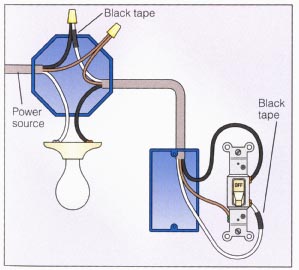
Wiring A Light Fixture 1 Wiring A Light Fixture 2 Wiring A Light.

Wiring Ceiling Light Decorative Ceiling Tiles Uk.
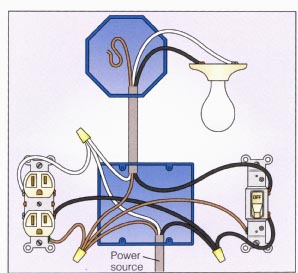
Wiring A Switched Outlet Wiring Diagram Power To Receptacle Ajilbab.
Outdoor Low Voltage Halogen Wall Lights Halogen Wall Lights Wdl820.

Outdoor Lighting Wiring Diagram 2 Gang Switch.

Fluorescent Light Fixture Wiring Diagram Submited Images Pic 2 Fly.

Wiring A Ceiling Light Images Best Pictures And Photos Samples Of.

Wiring A Double Light Switch Diagram Electrical Information Blog.

Loft Lighting Diydoctor Org Uk Diy And Home Improvement Forums.
Tuesday, December 18, 2012
Wiring light Switch Ceiling Light Project

Telephone Socket Wiring How To Do It.

Thread Wiring Clipsal Saturn Light Switches.

Mesa Whole House Wiring Services Provided By Amadeus Electric.

Multi Room Wiring.

Russell Residence 10007 Meadow Road Sw Lakewood Wa 98499.

Home House Wiring Installation.

250 And 525 Sx Mxc Exc Electrical System And Wiring Diagram Here.

Wiring A Switched Outlet Wiring Diagram Electrical Online.

Wiring A Light Switch For A Ceiling Light Diy Project.

In A Home Equipped With Lexcom Home Wiring Network Cabling System.
Saturday, December 8, 2012
Trailer Wiring Diagram Light Plug Brakes Hitch Wire Brake

Pulling The Band Trailer.

Looking To The Rear For The Trailer Plug The Pins Are Reversed And.

Trailer Wiring Diagram Light Plug Brakes Hitch 4 Pin Way Wire Brake.

Trailer Light Wiring Typical Trailer Light Wiring Diagram.

Trailer Parts Depot Trailer Wiring Kits Trailer Parts.
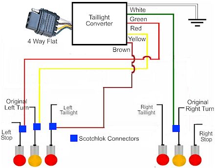
How To Install A Trailer Light Taillight Converter In Your Towing.

Wiring For 13 Pin Euro Plugs Sockets For Trailers Caravans Uk.

Trailer Wiring Diagram.

Wiring Color For 7 Pin Trailer Plug Jpg.

12s Wiring Diagram.
Friday, November 23, 2012
Wiring light Switch Ceiling Light Project
Telephone Socket Wiring How To Do It.
Thread Wiring Clipsal Saturn Light Switches.
Mesa Whole House Wiring Services Provided By Amadeus Electric.
Multi Room Wiring.
Russell Residence 10007 Meadow Road Sw Lakewood Wa 98499.
Home House Wiring Installation.
250 And 525 Sx Mxc Exc Electrical System And Wiring Diagram Here.
Wiring A Switched Outlet Wiring Diagram Electrical Online.
Wiring A Light Switch For A Ceiling Light Diy Project.
In A Home Equipped With Lexcom Home Wiring Network Cabling System.
Subscribe to:
Posts (Atom)