Showing posts with label build. Show all posts
Showing posts with label build. Show all posts
Saturday, December 21, 2013
Build A Synchronous Clock
The quartz clocks which have dominated time-keeping for the past 20 years or so have one problem: their errors, although slight, are cumulative. After running for several months the errors can be significant. Sometimes you can correct these if you can slightly tweak the crystal frequency but otherwise you are forced to reset the clock at regular intervals. By contrast, mains-powered synchronous clocks are kept accurate by the 50Hz mains distribution system and they are very reliable, except of course, when a blackout occurs. This circuit converts a quartz clock to synchronous mains operation, so that you can have at least one clock in your home which shows the time. First, you need to obtain a quartz clock movement and disassemble it down to the PC board. For instructions on how to do this, see the article on a "Fast Clock For Railway Modellers" in the December 1996 issue of SILICON CHIP. Then isolate the two wires to the clock coil and solder two light duty insulated hookup wires to them (eg, two strands of rainbow cable). Drill a small hole in the clock case and pass the wires through them. Then reassemble the clock case.

A Synchronous Clock Circuit Diagram
To test the movement, touch the wires to the terminals of an AA cell, then reverse the wires and touch the cell terminals again. The clock second hand should advance on each connection. The circuit is driven by a low voltage AC plug pack. Its AC output is fed to two bridge rectifiers: BR1 provides the DC supply while BR2 provides positive-going pulses at 100Hz to IC1a, a 4093 NAND Schmitt trigger. IC1a squares up the 100Hz pulses and feeds them to the clock input of the cascaded 4017 decade counters. The output at pin 12 of IC3 is 1Hz. This is fed to IC4, a 4013 D-type flipflop, which is connected so that its two outputs at pins 12 & 13 each go positive for one second at a time. As these pulses are too long to drive the clock movement directly, the outputs are each fed to 4093 NAND gates IC1b & IC1c where they are gated with the pin 3 signal to IC4. This results in short pulses from pins 3 & 10 of IC1 which drives the clock via limiting resistor R1. The value of R1 should be selected on test, allowing just enough current to reliably drive the clock movement.
Author: A. J. Lowe - Copyright: Silicon Chip
Source:
Wednesday, September 11, 2013
Build a Auto Anti Hijack Alarm Circuit Diagram
This Auto Anti-Hijack Alarm Circuit Diagram was designed primarily for the situation where a hijacker forces the driver from the vehicle. If a door is opened while the ignition is switched on - the circuit will trip. After a few minutes delay - when the thief is at a safe distance - the Siren will sound.

Where it differs from the first two alarms - is in what happens next. Im obliged to Victor Montanez from the USA who suggested that the engine cut-out should not operate - until the vehicle comes to a stop. That way - the engine will not fail suddenly or unexpectedly. And the hijacker will retain control.
I havent been able to implement Victors excellent suggestion completely - because I couldnt think of a simple, reliable and universally applicable way of sensing when the vehicle has come to a stop.
Instead - I have postponed engine failure until the ignition is switched off. Once the thief turns off the ignition - the engine will not re-start. Clearly - there is no certainty as to when this will occur. But I think it will occur sooner rather than later. Because theres a strong possibility that the hijacker will turn off the ignition - in an attempt to silence the siren.
Auto Anti-Hijack Alarm Circuit Diagram

As well as acting as a Hijack Alarm - this circuit offers some added protection. Like the Enhanced Hijack Alarm - it incorporates Jeff Chias suggestion. That is - every time the ignition is switched on - the alarm will trip. So it will protect the vehicle whenever you leave it unattended with the ignition switched off - even overnight in your driveway.
Importance
Before fitting this or any other engine cut-out to your vehicle - carefully consider both the safety implications of its possible failure - and the legal consequences of installing a device that could cause an accident. If you decide to proceed - you will need to use the highest standards of materials and workmanship.
Notes
Youre going to trip this alarm unintentionally. When you do - the LED will light and the Buzzer will give a short beep. The length of the beep is determined by C4. Its purpose is to alert you to the need to push the reset button. When you push the button - the LED will switch-off. Its purpose is to reassure you that the alarm has in fact reset.
If the reset button is not pressed then - about 3 minutes later - both the Siren and the Buzzer will sound continuously. The length of the delay is set by R8 & C5. For extra effect - fit a second siren inside the vehicle. With enough noise going on - you may feel that its unnecessary to fit the engine cut-out. In which case - you can leave out C7, D8, R12, R13, Ty1 & Ry2.
When the ignition is switched on - C3 & R4 are responsible for tripping the alarm. By taking pin 1 low momentarily - they simulate the opening of a door. If you dont want the alarm to trip every time you turn on the ignition - simply leave out C3 & R4.
Because the voltage on C3 may be reversed - the capacitor needs to be non-polarized. But connecting two regular 22uF capacitors back to back as shown - will work just as well. Because non-polarized capacitors are not widely available - the prototype was built using two polarized capacitors.
To reset the circuit you must - EITHER turn off the ignition - OR close all of the doors - before you press the reset button. While BOTH the ignition is on - AND a door remains open - the circuit will NOT reset.
The reset button carries virtually no current - so any small normally-open switch will do. Eric Vandel from Canada suggests using a reed-switch hidden behind (say) the dash - and operated by a magnet. I think this is an excellent idea. As Eric said in his email: - "... that should keep any thief guessing for a while."
Veroboard Layout

How you prevent the engine from starting is up to you. It should happen when Ry2 de-energizes. The contacts of Ry2 are too small to do the job themselves. So use them to switch the coil of a larger relay. Remember that the relay must be suitable for the current its required to carry. Choose one specifically designed for automobiles - it will be protected against the elements - and will give the best long-term reliability. You dont want it to let you down on a cold wet night - or worse still - in fast moving traffic!!! Remember also that you must fit a 1N4001 diode across YOUR relays coil - to prevent damage to the Cmos IC
YOUR relay should drop-out when Ry2 de-energizes. Wire YOUR relay so that when it drops-out the engine will not start. Because turning-off the ignition will cause both Ry2 and YOUR relay to de-energize - the standby current will be low - and the engine will be disabled while the vehicle is parked.
The circuit board must be protected from the elements. Dampness or condensation will cause malfunction. Fit a 1-amp in-line fuse AS CLOSE AS POSSIBLE to your power source. This is VERY IMPORTANT. The fuse is there to protect the wiring - not the components on the circuit board. Please note that I am UNABLE to help any further with either the choice of a suitable relay - or with advice on installation.
Both the Siren and the Buzzer will go on sounding until the alarm is reset. The circuit is designed to use an electronic Siren drawing up to about 500mA. Its not usually a good idea to use the vehicles own Horn because it can be easily located and disconnected. However, if you choose to use the Horn, remember that Ry1 is too small to carry the necessary current. Connect the coil of a suitably rated relay to the "Siren" output. This can then be used to sound the Horn.
Wednesday, September 4, 2013
Build an op amp with three Discrete Transistors
You can use three discrete transistors to build an operational amplifier with an open-loop gain greater than 1 million (Figure 1). You bias the output at approximately one-half the supply voltage using the combined voltage drops across zener diode D1, the emitter-base voltage of input transistor Q1, and the 1V drop across 1-MΩ feed-back resistor R2.
Resistor R3 and capacitor C1 form a compensation network that prevents the circuit from oscillating. The values in the figure still provide a good square-wave response. The ratio of R2 to R1 determines the inverting gain, which is −10 in this example.
You can configure this op amp as an active filter or as an oscillator. It drives a load of 1 kΩ. The square-wave response is good at 10 kHz, and the output reduces by 3 dB at 50 kHz. Set the 50-Hz low-frequency response with the values of the input and the output capacitors. You can raise the high-frequency response by using faster transistors and doing careful layout. Link
 | |
| Figure 1. | This ac-coupled inverting op amp has an open-loop gain of 1 million. R1 and R2 set a closed-loop gain of −10. |
Resistor R3 and capacitor C1 form a compensation network that prevents the circuit from oscillating. The values in the figure still provide a good square-wave response. The ratio of R2 to R1 determines the inverting gain, which is −10 in this example.
You can configure this op amp as an active filter or as an oscillator. It drives a load of 1 kΩ. The square-wave response is good at 10 kHz, and the output reduces by 3 dB at 50 kHz. Set the 50-Hz low-frequency response with the values of the input and the output capacitors. You can raise the high-frequency response by using faster transistors and doing careful layout. Link
Sunday, November 18, 2012
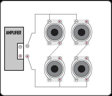
Wiring Dual Coil Build Trinituner

Subwoofer Wiring Diagrams Four 4 Ohm Dual Voice Coil Dvc Speakers.

Discuss Ep4000 Maelstrom X Ii In The Diy Subwoofers Forum.

300w Subwoofer Power Amplifier Wiring Diagram Skema Rangkaian.
Audio Systems Subwoofer Wiring Monoblock Amp Watts Rms.

Bazooka Subwoofer Wiring Diagram.

Subwoofer Wiring Diagrams Two 8 Ohm Single Voice Coil Svc Speakers.
Need Sum Help Wiring Dual Coil Sub And Box Build Trinituner Com.

Sub 2 Output Is An Excellent Way To Connect Your Subwoofers The Total.

Subwoofer Wiring Diagrams Subwoofers And Other Stereo Equipment.

Audio Savings Kicker Vcvr15 2 15 Car Subwoofer Enclosure Kicker.
Subscribe to:
Posts (Atom)