Showing posts with label remote. Show all posts
Showing posts with label remote. Show all posts
Saturday, October 5, 2013
Infrared Remote Receiver Has Four Outputs
This circuit enables any infrared (IR) remote control to control the outputs of a 4017 decade counter. Its quite simple really and uses a 3-terminal IR receiver (IRD1) to pick up infrared signals from the transmitter. IRD1s output is then coupled to NPN transistor Q1 via a 220nF capacitor. Transistor Q1 functions as a common-emitter amplifier with a gain of about 20, as set by the ratio of its 10kO collector resistor to its 470O emitter resistor. Q1 in turn triggers IC1, a 4047 monostable which in turn clocks a 4017 decade counter (IC2).

Basically, IC1 provides a clock pulse to IC2 each time a remote control button is pressed. If you dont wish to use all 10 outputs from IC2, simply connect the first unused output to pin 15 (MR). In this case, only the first four outputs (O0-O3) of the counter are used and so the O4 output is connected to pin 15 to reset the counter on the fifth button press. Power for the circuit is derived from the mains via a transformer and bridge rectifier which produces about 15-27V DC. This is then fed to 3-terminal regulators REG1 & REG2 to derive +12V and +5V supply rails.
Readmore...

Basically, IC1 provides a clock pulse to IC2 each time a remote control button is pressed. If you dont wish to use all 10 outputs from IC2, simply connect the first unused output to pin 15 (MR). In this case, only the first four outputs (O0-O3) of the counter are used and so the O4 output is connected to pin 15 to reset the counter on the fifth button press. Power for the circuit is derived from the mains via a transformer and bridge rectifier which produces about 15-27V DC. This is then fed to 3-terminal regulators REG1 & REG2 to derive +12V and +5V supply rails.

Wednesday, September 4, 2013
IR Remote Control Extender Mark 2
This is an improved IR remote control extender circuit. It has high noise immunity, is resistant to ambient and reflected light and has an increased range from remote control to the extender circuit of about 7 meters. It should work with any domestic apparatus that use 36-38kHz for the IR carrier frequency. Please note that this is NOT compatible with some satellite receivers that use 115KHz as a carrier frequency.

Notes:
The main difference between this version and the previous circuit, is that this design uses a commercially available Infra Red module. This module, part number IR1 is available from Harrison Electronics in the UK. The IR module contains a built in photo diode, amplifier circuit and buffer and decoder. It is centerd on the common 38kHz carrier frequency that most IR controls use. The module removes most of the carrier allowing decoded pulses to pass to the appliance. Domestic TVs and VCRs use extra filtering is used to completely remove the carrier. The IR1 is packaged in a small aluminium case, the connections viewed from underneath are shown below:
Infra Red Module, IR1 Pinout
How It works:
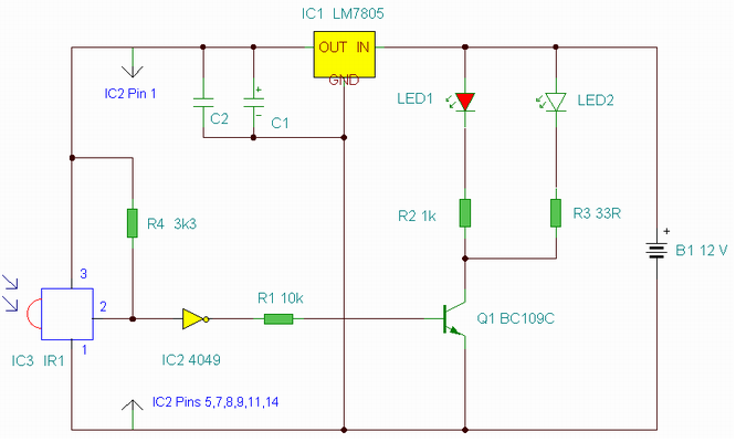
The IR1 module (IC3) operates on 5 Volt dc. This is provided by the 7805 voltage regulator, IC1. Under quiescent (no IR signal) conditions the voltage on the output pin is high, around 5 volts dc. This needs to be inverted and buffered to drive the IR photo emitter LED, LED2. The buffering is provided by one gate (pins 2 & 3) of a hex invertor the CMOS 4049, IC2. The IR1 module can directly drive TTL logic,but a pull-up resistor, R4 is required to interface to CMOS ICs. This resistor ensures that the signal from a remote control will alternate between 0 and 5 volts. As TTL logic levels are slightly different from CMOS, the 3.3k resistor R4 is wired to the +5 volt supply line ensuring that the logic high signal will be 5 volts and not the TTL levels 3.3 volts. The resistor does not affect performance of the IR module, but DOES ensure that the module will correctly drive the CMOS buffer without instability.
The output from the 4049 pin 2 directly drives transistor Q1, the 10k resistor R1 limiting base current. LED1 is a RED LED, it will flicker to indicate when a signal from a remote control is received. Note that in this circuit, the carrier is still present, but at a reduced level, as well as the decoded IR signal. The CMOS 4049 and BC109C transistor will amplify both carrier and signal driving LED2 at a peak current of about 120 mA when a signal is received. If you try to measure this with a digital meter, it will read much less, probably around 30mA as the meter will measure the average DC value, not the peak current. Any equipment designed to work between 36 and 40kHz should work, any controls with carrier frequencies outside this limit will have reduced range, but should work. The exception here is that some satellite receivers have IR controls that use a higher modulated carrier of around 115KHz. At present, these DO NOT work with my circuit, however I am working on a Mark 3 version to re-introduce the carrier.
Parts List:
C1 100u 10V
C2 100n polyester
R1 10k
R2 1k
R3 33R 1W
R4 3k3
Q1 BC109C
IC1 LM7805
IC2 CMOS 4049B
IC3 IR1 module from Harrison Electronics See Last paragraph
LED1 Red LED (or any visible colour)
LED2 TIL38 or part YH70M from Maplin Electronics
Testing:
This circuit should not present too many problems. If it does not work, arm yourself with a multimeter and perform these checks. Check the power supply for 12 Volt dc. Check the regulator output for 5 volt dc. Check the input of the IR module and also Pin 1 of the 4049 IC for 5 volts dc. With no remote control the output at pin 2 should be zero volts. Using a remote control pin 2 will read 5 volts and the Red LED will flicker. Measuring current in series with the 12 volt supply should read about 11mA quiescent, and about 40/50mA with an IR signal. If you still have problems measure the voltage between base and emitter of Q1. With no signal this should be zero volts, and rise to 0.6-0.7 volts dc with an IR signal. Any other problems, please email me, but please do the above tests first.
PCB Template:
Once again a PCB template has been kindly drafted for this project by Domenico.

A magnified view showing the component side is shown below:

Alternatives to IC3:
The part number IR1 from Harrison Electronics is no longer available. They do supply an alternative IR decoder which I have tested and works. Other alternative Infrared decoders are shown below, note however that all DO NOT share the same pinout. I advise anyone making this to check the corresponding data sheets.
Vishay TSOP 1738
Vishay TSOP 1838
Radio Shack 276-0137
Sony SBX 1620-12
Sharp GP1U271R
Equipment Controlled Successfully:
If you have built this circuit and it works successfullt please let me know and I will build the list. Email details of the Manufacturer, device and remote control model number. The remote model number is usually on the front or back of the remote.
Technics CDP770 Remote: EUR64713
Notes:
The main difference between this version and the previous circuit, is that this design uses a commercially available Infra Red module. This module, part number IR1 is available from Harrison Electronics in the UK. The IR module contains a built in photo diode, amplifier circuit and buffer and decoder. It is centerd on the common 38kHz carrier frequency that most IR controls use. The module removes most of the carrier allowing decoded pulses to pass to the appliance. Domestic TVs and VCRs use extra filtering is used to completely remove the carrier. The IR1 is packaged in a small aluminium case, the connections viewed from underneath are shown below:
Infra Red Module, IR1 Pinout
How It works:
The IR1 module (IC3) operates on 5 Volt dc. This is provided by the 7805 voltage regulator, IC1. Under quiescent (no IR signal) conditions the voltage on the output pin is high, around 5 volts dc. This needs to be inverted and buffered to drive the IR photo emitter LED, LED2. The buffering is provided by one gate (pins 2 & 3) of a hex invertor the CMOS 4049, IC2. The IR1 module can directly drive TTL logic,but a pull-up resistor, R4 is required to interface to CMOS ICs. This resistor ensures that the signal from a remote control will alternate between 0 and 5 volts. As TTL logic levels are slightly different from CMOS, the 3.3k resistor R4 is wired to the +5 volt supply line ensuring that the logic high signal will be 5 volts and not the TTL levels 3.3 volts. The resistor does not affect performance of the IR module, but DOES ensure that the module will correctly drive the CMOS buffer without instability.
The output from the 4049 pin 2 directly drives transistor Q1, the 10k resistor R1 limiting base current. LED1 is a RED LED, it will flicker to indicate when a signal from a remote control is received. Note that in this circuit, the carrier is still present, but at a reduced level, as well as the decoded IR signal. The CMOS 4049 and BC109C transistor will amplify both carrier and signal driving LED2 at a peak current of about 120 mA when a signal is received. If you try to measure this with a digital meter, it will read much less, probably around 30mA as the meter will measure the average DC value, not the peak current. Any equipment designed to work between 36 and 40kHz should work, any controls with carrier frequencies outside this limit will have reduced range, but should work. The exception here is that some satellite receivers have IR controls that use a higher modulated carrier of around 115KHz. At present, these DO NOT work with my circuit, however I am working on a Mark 3 version to re-introduce the carrier.
Parts List:
C1 100u 10V
C2 100n polyester
R1 10k
R2 1k
R3 33R 1W
R4 3k3
Q1 BC109C
IC1 LM7805
IC2 CMOS 4049B
IC3 IR1 module from Harrison Electronics See Last paragraph
LED1 Red LED (or any visible colour)
LED2 TIL38 or part YH70M from Maplin Electronics
Testing:
This circuit should not present too many problems. If it does not work, arm yourself with a multimeter and perform these checks. Check the power supply for 12 Volt dc. Check the regulator output for 5 volt dc. Check the input of the IR module and also Pin 1 of the 4049 IC for 5 volts dc. With no remote control the output at pin 2 should be zero volts. Using a remote control pin 2 will read 5 volts and the Red LED will flicker. Measuring current in series with the 12 volt supply should read about 11mA quiescent, and about 40/50mA with an IR signal. If you still have problems measure the voltage between base and emitter of Q1. With no signal this should be zero volts, and rise to 0.6-0.7 volts dc with an IR signal. Any other problems, please email me, but please do the above tests first.
PCB Template:
Once again a PCB template has been kindly drafted for this project by Domenico.


The part number IR1 from Harrison Electronics is no longer available. They do supply an alternative IR decoder which I have tested and works. Other alternative Infrared decoders are shown below, note however that all DO NOT share the same pinout. I advise anyone making this to check the corresponding data sheets.
Vishay TSOP 1738
Vishay TSOP 1838
Radio Shack 276-0137
Sony SBX 1620-12
Sharp GP1U271R
Equipment Controlled Successfully:
If you have built this circuit and it works successfullt please let me know and I will build the list. Email details of the Manufacturer, device and remote control model number. The remote model number is usually on the front or back of the remote.
Technics CDP770 Remote: EUR64713
Tuesday, September 3, 2013
TV Remote Control Jammer
This circuit confuses the infra-red receiver in a TV. It produces a constant signal that interferes with the signal from a remote control and prevents the TV detecting a channel-change or any other command. This allows you to watch your own program without anyone changing the channel !! The circuit is adjusted to produce a 38kHz signal. The IR diode is called an Infra-red transmitting Diode or IR emitter diode to distinguish it from a receiving diode, called an IR receiver or IR receiving diode. (A Photo diode is a receiving diode).
TV Remote Control Jammer Circuit diagram:

There are so many IR emitters that we cannot put a generic number on the circuit to represent the type of diode. Some types include: CY85G, LD271, CQY37N (45¢), INF3850, INF3880, INF3940 (30¢). The current through the IR LED is limited to 100mA by the inclusion of the two 1N4148 diodes, as these form a constant-current arrangement when combined with the transistor and 5R6 resistor.
TV Remote Control Jammer Circuit diagram:

There are so many IR emitters that we cannot put a generic number on the circuit to represent the type of diode. Some types include: CY85G, LD271, CQY37N (45¢), INF3850, INF3880, INF3940 (30¢). The current through the IR LED is limited to 100mA by the inclusion of the two 1N4148 diodes, as these form a constant-current arrangement when combined with the transistor and 5R6 resistor.
Saturday, August 31, 2013
Digital Remote Thermometer Circuit
Description

Transmitter parts:
 Receiver Parts:
Notes:
Readmore...
This circuit is intended for precision centigrade temperature measurement, with a transmitter section converting to frequency the sensors output voltage, which is proportional to the measured temperature. The output frequency bursts are conveyed into the mains supply cables. The receiver section counts the bursts coming from mains supply and shows the counting on three 7-segment LED displays. The least significant digit displays tenths of degree and then a 00.0 to 99.9 °C range is obtained. Transmitter-receiver distance can reach hundred meters, provided both units are connected to the mains supply within the control of the same light-meter.
Transmitter Circuit Operation:IC1 is a precision centigrade temperature sensor with a linear output of 10mV/°C driving IC2, a voltage-frequency converter. At its output pin (3), an input of 10mV is converted to 100Hz frequency pulses. Thus, for example, a temperature of 20°C is converted by IC1 to 200mV and then by IC2 to 2KHz. Q1 is the driver of the power output transistor Q2, coupled to the mains supply by L1 and C7, C8.
Circuit Diagram:

- R1 = 100K 1/4W Resistors
- R2 = 47R 1/4W Resistor
- R3 = 100K 1/4W Resistors
- R4 = 5K 1/2W Trimmer Cermet
- R5 = 12K 1/4W Resistor
- R6 = 10K 1/4W Resistor
- R7 = 6K8 1/4W Resistor
- R8 = 1K 1/4W Resistors
- R9 = 1K 1/4W Resistors
- C1 = 220nF 63V Polyester Capacitor
- C2 = 10nF 63V Polyester Capacitor
- C3 = 1µF 63V Polyester Capacitor
- C4 = 1nF 63V Polyester Capacitors
- C5 = 2n2 63V Polyester Capacitor
- C6 = 1nF 63V Polyester Capacitors
- C7 = 47nF 400V Polyester Capacitors
- C8 = 47nF 400V Polyester Capacitors
- C9 = 1000µF 25V Electrolytic Capacitor
- D1 = 1N4148 75V 150mA Diode
- D2 = 1N4002 100V 1A Diodes
- D3 = 1N4002 100V 1A Diodes
- D4 = 5mm. Red LED
- IC1 = LM35 Linear temperature sensor IC
- IC2 = LM331 Voltage-frequency converter IC
- IC3 = 78L06 6V 100mA Voltage regulator IC
- Q1 = BC238 25V 100mA NPN Transistor
- Q2 = BD139 80V 1.5A NPN Transistor
- T1 = 220V Primary, 12+12V Secondary 3VA Mains transformer
- PL = Male Mains plug & cable
- L1 = Primary (Connected to Q2 Collector): 100 turns
- Secondary: 10 turns
- Wire diameter: O.2mm. enameled
- Plastic former with ferrite core. Outer diameter: 4mm
The frequency pulses coming from mains supply and safely insulated by C1, C2 & L1 are amplified by Q1; diodes D1 and D2 limiting peaks at its input. Pulses are filtered by C5, squared by IC1B, divided by 10 in IC2B and sent for the final count to the clock input of IC5. IC4 is the time-base generator: it provides reset pulses for IC1B and IC5 and enables latches and gate-time of IC5 at 1Hz frequency. It is driven by a 5Hz square wave obtained from 50Hz mains frequency picked-up from T1 secondary, squared by IC1C and divided by 10 in IC2A. IC5 drives the displays cathodes via Q2, Q3 & Q4 at a multiplexing rate frequency fixed by C7. It drives also the 3 displays paralleled anodes via the BCD-to-7 segment decoder IC6. Summing up, input pulses from mains supply at, say, 2KHz frequency, are divided by 10 and displayed as 20.0°C.
Circuit Diagram:
- R1 = 100K 1/4W Resistor
- R2 = 1K 1/4W Resistor
- R3 = 12K 1/4W Resistors
- R4 = 12K 1/4W Resistors
- R5 = 47K 1/4W Resistor
- R6 = 12K 1/4W Resistors
- R8 = 12K 1/4W Resistors
- R9-R15=470R 1/4W Resistors
- R16 = 680R 1/4W Resistor
- C1 = 47nF 400V Polyester Capacitors
- C2 = 47nF 400V Polyester Capacitors
- C3 = 1nF 63V Polyester Capacitors
- C4 = 10nF 63V Polyester Capacitor
- C7 = 1nF 63V Polyester Capacitors
- C5 = 220nF 63V Polyester Capacitors
- C6 = 220nF 63V Polyester Capacitors
- C8 = 1000µF 25V Electrolytic Capacitor
- C9 = 100pF 63V Ceramic Capacitor
- C10 = 220nF 63V Polyester Capacitors
- D1 = 1N4148 75V 150mA Diodes
- D2 = 1N4148 75V 150mA Diodes
- D3 = 1N4002 100V 1A Diodes
- D4 = 1N4002 100V 1A Diodes
- D5 = 1N4148 75V 150mA Diodes
- D6 = Common-cathode 7-segment LED mini-displays
- D7 = Common-cathode 7-segment LED mini-displays
- D8 = Common-cathode 7-segment LED mini-displays
- IC1 = 4093 Quad 2 input Schmitt NAND Gate IC
- IC2 = 4518 Dual BCD Up-Counter IC
- IC3 = 78L12 12V 100mA Voltage regulator IC
- IC4 = 4017 Decade Counter with 10 decoded outputs IC
- IC5 = 4553 Three-digit BCD Counter IC
- IC6 = 4511 BCD-to-7-Segment Latch/Decoder/Driver IC
- Q1 = BC239C 25V 100mA NPN Transistor
- Q2 = BC327 45V 800mA PNP Transistors
- Q3 = BC327 45V 800mA PNP Transistors
- Q4 = BC327 45V 800mA PNP Transistors
- PL = Male Mains plug & cable
- T1 = 220V Primary, 12+12V Secondary 3VA Mains transformer
- L1 = Primary (Connected to C1 & C2): 10 turns
- Secondary: 100 turns
- Wire diameter: O.2mm. enameled
- Plastic former with ferrite core. Outer diameter: 4mm.
- D6 is the Most Significant Digit and D8 is the Least Significant Digit.
- R16 is connected to the Dot anode of D7 to illuminate permanently the decimal point.
- Set the ferrite cores of both inductors for maximum output (best measured with an oscilloscope, but not critical).
- Set trimmer R4 in the transmitter to obtain a frequency of 5KHz at pin 3 of IC2 with an input of 0.5Vcc at pin 7 (a digital frequency meter is required).
- More simple setup: place a thermometer close to IC1 sensor, then set R4 to obtain the same reading of the thermometer in the receivers display.
- Keep the sensor (IC1) well away from heating sources (e.g. Mains Transformer T1).
- Linearity is very good.
- Warning! Both circuits are connected to 230Vac mains, then some parts in the circuit boards are subjected to lethal potential! Avoid touching the circuits when plugged and enclose them in plastic boxes.
Friday, November 16, 2012
Typical Ceiling Remote Control Wired Shown Wiring

Ceiling Fan Wiring Diagram 2 S.

Hampton Bay Ceiling Fan Wiring Diagram Group Picture Image By Tag.

Ceiling Fan Wiring Design Ideas Pictures Pictures Photos Images.

Typical Ceiling Fan Remote Control Is Wired As Shown In This Wiring.

Ceiling Fan Wiring Circuit Style 12.

Ceiling Fan Wiring Circuit Style 9.

Research A Variety Of Ceiling Fans Within The Lighting Ceiling Fans.

Ceiling Fan Wiring Photos Pictures Images Design Ideas Pictures.

Jimmy Trucks And Suburban Enthusiasts Ceiling Fan Wiring Diagram.

Wiring For A Ceiling Fan With Dual Switches Electrical Diy.
Subscribe to:
Posts (Atom)