Showing posts with label fuse. Show all posts
Showing posts with label fuse. Show all posts
Thursday, January 9, 2014
Electronic Fuse Employs A Relay
While many power supplies can be set to limit their output current to a defined level, to protect the circuit they are powering, no such protection is available if you are powering a circuit from a battery. If a fault develops, the circuit can blow before you have a chance to disconnect it. Of course, you can fit a fuse in series with the supply line to the circuit under test but it will blow if a fault develops. Or perhaps it won’t blow sufficiently quickly to protect the circuit. And repeatedly having to replace fuses becomes a nuisance as well.

The alternative is to use an electronic fuse. This circuit uses a relay to make and break the circuit. The current drain of the circuit under test is monitored by a 1O 2W resistor which is placed in series with the supply line. The voltage across this 1O resistor is monitored by op amp IC1a which has an adjustable gain of between 11 and 16, as set by trimpot VR1. The resultant DC voltage from pin 1 of IC1a is fed to pin 5 of IC1b which is configured as a comparator.
Trimpot VR2 provides an adjustable voltage reference to pin 6 of IC1b and this is compared with the amplified signal from IC1a. If IC1b’s threshold is exceeded, its pin 7 goes high and this is fed to Schmitt trigger inverter IC2a which then “sets” the RS flipflop comprising gates IC2c & IC2d. Pin 11 of IC2d then goes high to turn on transistor Q2 and LED1 while pin 4 of IC2b also goes high to turn on Q1 and the relay which then disconnects the load.
The circuit stays in this state until the RS flipflop is reset by pushing switch S1. Capacitor Cx, across the feedback resistance of IC1a, is used to simulate a slow-blow or fast-blow fuse and can be selected by trial and error. Changing the gain of IC1a or the value of the sensing resistor changes the fuse rating of the circuit.
Readmore...

The alternative is to use an electronic fuse. This circuit uses a relay to make and break the circuit. The current drain of the circuit under test is monitored by a 1O 2W resistor which is placed in series with the supply line. The voltage across this 1O resistor is monitored by op amp IC1a which has an adjustable gain of between 11 and 16, as set by trimpot VR1. The resultant DC voltage from pin 1 of IC1a is fed to pin 5 of IC1b which is configured as a comparator.
Trimpot VR2 provides an adjustable voltage reference to pin 6 of IC1b and this is compared with the amplified signal from IC1a. If IC1b’s threshold is exceeded, its pin 7 goes high and this is fed to Schmitt trigger inverter IC2a which then “sets” the RS flipflop comprising gates IC2c & IC2d. Pin 11 of IC2d then goes high to turn on transistor Q2 and LED1 while pin 4 of IC2b also goes high to turn on Q1 and the relay which then disconnects the load.
The circuit stays in this state until the RS flipflop is reset by pushing switch S1. Capacitor Cx, across the feedback resistance of IC1a, is used to simulate a slow-blow or fast-blow fuse and can be selected by trial and error. Changing the gain of IC1a or the value of the sensing resistor changes the fuse rating of the circuit.

Friday, September 20, 2013
Fuse Box BMW 1973 Diagram
Fuse Box BMW 1973 Diagram - Here are new post for Fuse Box BMW 1973 Diagram.
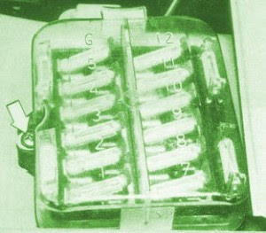

Fuse Panel Layout Diagram Parts: main electrical equipment, cigar lighter, hazard warning flasher, interior light, clock, heated rear window, wiper and windshield washer, brake light, turn indicator, reversing light, parking light, license plate light, oil pressure telltale lamp, revolution counter, handbrake telltale.
Readmore...
Fuse Box BMW 1973 Diagram


Fuse Panel Layout Diagram Parts: main electrical equipment, cigar lighter, hazard warning flasher, interior light, clock, heated rear window, wiper and windshield washer, brake light, turn indicator, reversing light, parking light, license plate light, oil pressure telltale lamp, revolution counter, handbrake telltale.
Thursday, September 19, 2013
Fuse Box BMW 2000 328i Central Diagram
Fuse Box BMW 2000 328i Central Diagram - Here are new post for Fuse Box BMW 2000 328i Central Diagram.


Fuse Panel Layout Diagram Parts: ABS system, adjustment driver seat, adjusment passenger seat, air bag, air conditioner, blower, brake light, central locking system, cigar lighter, electric fan, electric seat heating, engine control, folding outside mirror, fog light, garage door opener, heated outside mirror, heated rear window, heated spray nozzle, horn, immobilizer, instrument cluster.
Readmore...
Fuse Box BMW 2000 328i Central Diagram


Fuse Panel Layout Diagram Parts: ABS system, adjustment driver seat, adjusment passenger seat, air bag, air conditioner, blower, brake light, central locking system, cigar lighter, electric fan, electric seat heating, engine control, folding outside mirror, fog light, garage door opener, heated outside mirror, heated rear window, heated spray nozzle, horn, immobilizer, instrument cluster.
Subscribe to:
Posts (Atom)